


As always, click the picture to see a larger version. Stay tuned for more!


 |
| Hardware |
 |
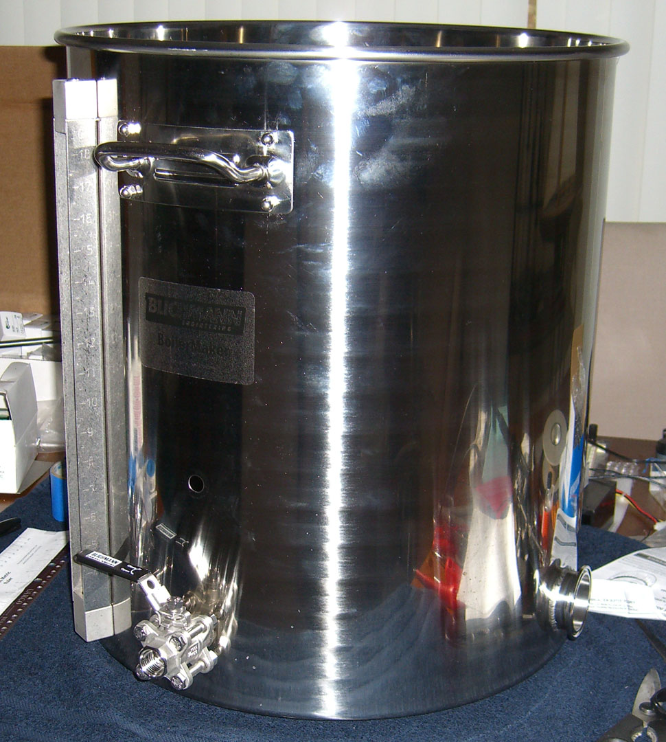
| Brew Kettles |


 |
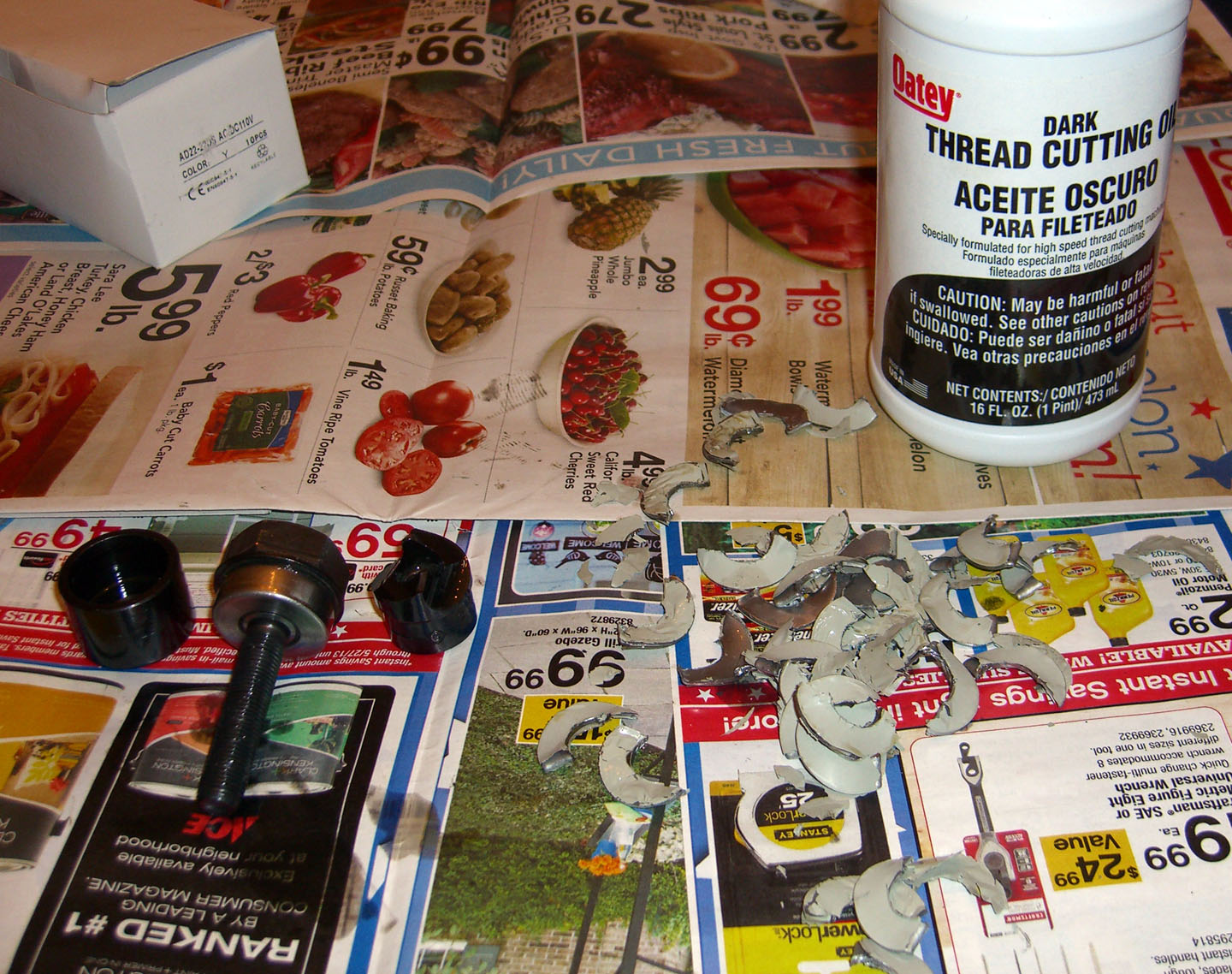
Laying out components |
 |
Holes for power meter and PIDs cut |
 |
Switch and LED holes drilled to 3/8" |

 |
SSRs and Heatsinks |
 |
Measuring holes for SSRs |
 |
Holes cut for SSRs |

