Building my HERMS Brewery. HERMS stands for Heat Exchanged Recirculating Mash. In my case it is an EHERMS or Electric HERMS system that will run on 240V using 5500W water heater elements and will brew 10 gallon batches.
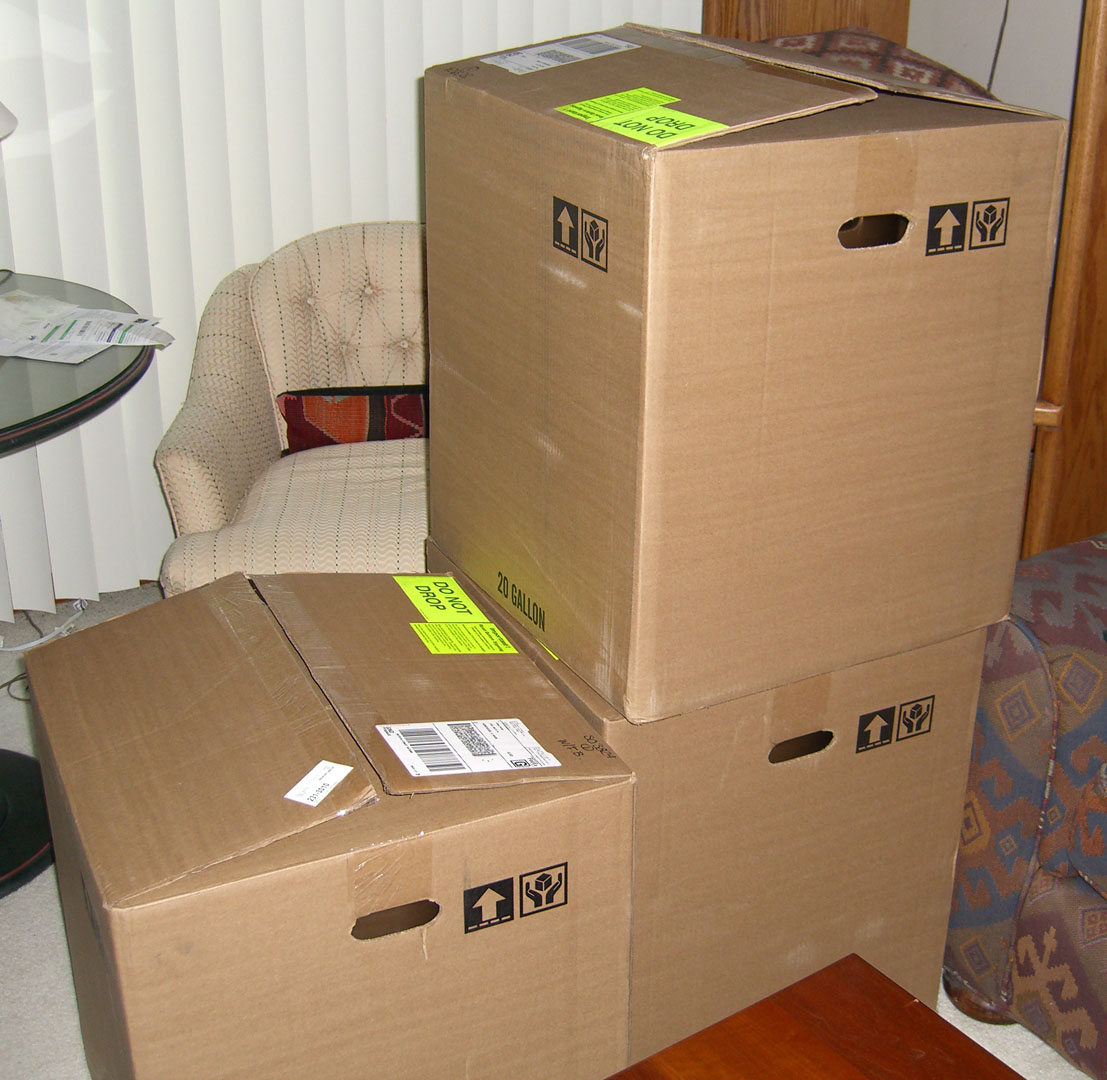
I got in most of the hardware for the kettles and plumbing recently. Still don't have the herms coil in but that should be here in the next few days. This is all the shutoff valves, quick disconnects, tees for probe connections, compression fittings for the herms coil and all liquid return hardware. Also got the brew kettles in.
Sucks. I hate it. Such a mess and stink. I'd do it outside if the humidity wasn't so bad but because of it I have been in the basement. To cut down on the overspray mess the goes everywhere I built a bit of a rig to capture the spray mist. It's an old monitor carton that I have taped a furnace filter on one end. There is a box fan next to the filter that pulls the air and spray through the filter and (hopefully) captures most of it.
The enclosure came with a rough textured finish that I am not really fond of so I started by sanding the surface down to remove the roughness and make it flat but not removing all the paint. I then applied some primer. I followed that with a couple coats of gloss black paint. I carefully sanded with 1000 grit sandpaper between coats. The last black basecoat was applied very carefully because it isn't sanded. This will be followed up by a few coats of clear but I have not done that yet. Many people add their labels using plastic tags purchased from a sign shop. I decided to try to do it a different way using water slide decals. I got some laser printable decal sheets and printed out all the labels on it. The sheet is basically one giant white decal. I printed out the labels in black leaving the text clear, which will let the white show through.
I then cut out each label with scissors as close to the lettering as I could. I wanted limit the amount of the black in the label as much as I could. Cutting through the black tended to leave a bit of the white background showing through on the edges so I used a black sharpie pen to hit the edges to cover any of the white decal showing through on the edges. This worked really well actually.
Applying the decals is pretty easy. Just soak it in lukewarm water for 30 seconds or so until you feel the decal can slide off the backing. Then slide it about a quarter of the way off and place that edge where you want it and then hold that part onto the surface and slide the backing out from behind it. When there is a layer of water under the decal you can easily slide it around to get it exactly where you want it. Then just pat it down with a clean rag or a paper towel. I also applied a layer of decal set to the surface to help the decal 'melt' onto the surface. It is not something you have to do but it helps the decal stick to the surface more. If the surface is sort of uneven or has a texture the decal set with soften the decal and make it fall down into the texture. Here are a couple pictures after I placed all the labels on the front. I still have to do the bottom. The panel is a gloss black and it is hard to get a good picture of because of the glare. It looks sort of gray or silver in the pictures but is actually really black. You can still see the black part of the decal contrast from the surface of the panel at this point because it is more dull then the rest of the panel. There will be a layer of gloss clear that goes over the panel next that will help hide these dull areas. The clear will also protect the labels from wear as well as gloss over the dullness.
I wasn't sure how well this whole thing would work before I started and if it didn't work out I would have fallen back on going with plastic tags. So far I am really pleased with how it has worked out. In real life it looks great so far. Should look awesome once i get the clear coat on it. More to come.
The control panel is the most important and most complicated part of the brewery. It will monitor and control temperatures, control pumps, as well as provide timers and alarms for specific events. Temperatures will be controlled by three PIDs or proportional-integral-derivative controllers. The ones I'm using are Auber SYL-2352 PIDs and the timer is a Auber JSL-71. The control panel is a watertight steel enclosure 16"(400mm)W X 16"(400mm)H X 8"(200mm)D with a back plate. Here is a slightly cutoff picture of it before I started working on it. I forgot to take a picture of it before I started.
This panel will house all the electrical components and have all the controls and switches for the major brewery operations. The first thing I did was sand the box to remove the top layer of the textured paint that was on it. First thing was to decide how everything would be arranged on the panel. I covered the top with painters tape to protect the face when I would be cutting the panel and marked all the locations where I was going to be adding components.
Laying out components
Holes for power meter and PIDs cut
Switch and LED holes drilled to 3/8"
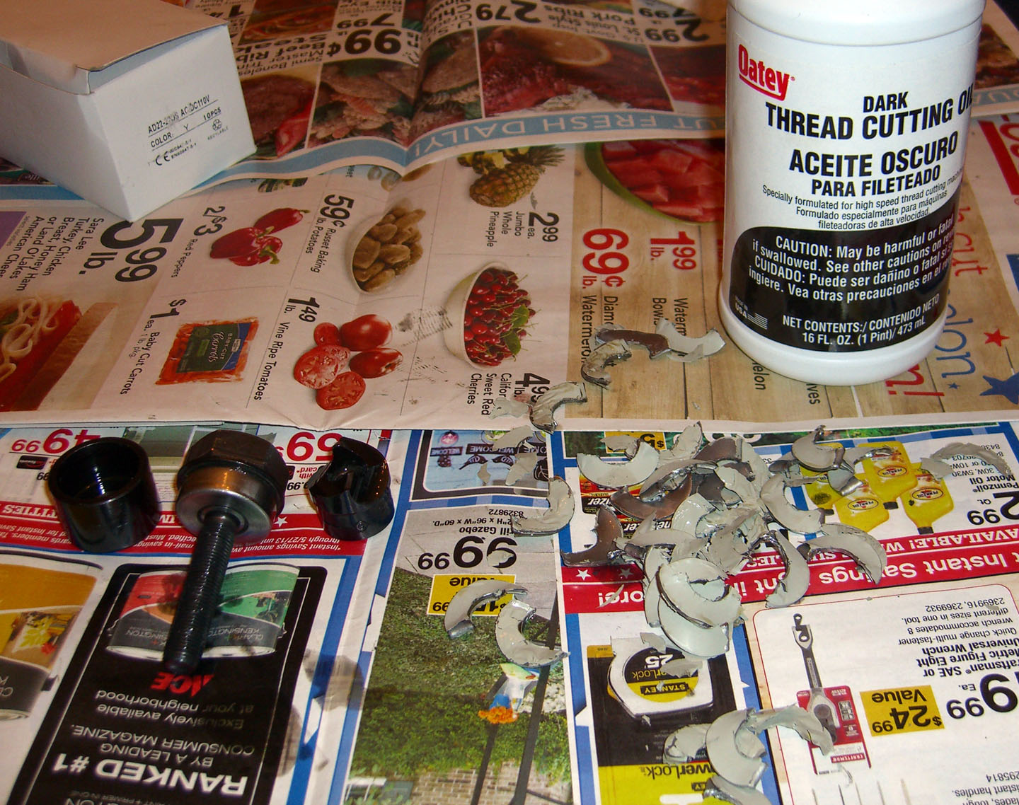
Holes for switches and LEDs need to be 22mm or about 7/8" in diameter. Drilling 7/8" holes can be quite a pain but luckily there is a perfect tool to handle this. A Greenlee 1/2" conduit knockout punch which cuts perfect 7/8" holes easily. The picture below shows the punch and the bits of scrap that were cutout.
Here is the front of the panel after the holes a punched.
There will be two SSRs (Solid State Relays) used to switch high current on and off to the main heating elements. These need rather large heatsinks as they generate a lot of heat we don't want trapped in the control panel. To remedy this we will mount the heatsinks outside the box on the top with the SSRs inside the box through holes cut in the top. Here are pictures of the SSRs and the heatsinks the holes in the top of the box.
SSRs and Heatsinks
Measuring holes for SSRs
Holes cut for SSRs
The holes for the SSRs don't look that great but it doesn't matter as they will be covered by the heatsinks. All the wiring into and out of the control panel will be in the bottom of the control panel. This will be the main power in, two outputs to heating elements, Two outputs to pumps, and three connections for temperature probes. Here is a picture of the bottom with all the holes cut.
Now it's time to paint this thing. It will be painted gloss black. Here is a picture of the unit all ready for paint.
That's as far as I am at this point on the control panel. I will add more as I progress. Stay tuned!
A lot of my build is based on ideas and work done by brewers on Homebrewtalk. One of the members there Kal, has also put up a wonderful site documenting his build at The Electric Brewery. To add a little flare to my control panel I have built a LED lighted version of Kal's logo. The panel is not finished yet but here is the Logo so far.
This will be attached to the back of the control panel face and will show through a hole cut in the panel. There will also be a small frame around it. This is how I built it.....
I started by printing out Kal's logo as a mirror image. It needs to be mirrored because you will be engraving it from the other side and that way it will be the correct way around when you are done. I cut 2 pieces of 1/8in acrylic to the proper size. I used a dremmel tool with the flex extension and a 1/32in engraving bit to 'etch' the image. The flex tool allows you to use the dremmel sort of like a pencil.
I then attached the printed logo using some tape and went over the image with the engraving tool. It takes a little practice at first because the image is seen though the thickness of the acrylic. You do not have to go very deep. Just go over the image slowly and cover everything. Be careful because the tool wants to 'pull' in the direction of the spin. It may be useful to practice on a scrap piece first. I did the lettering on one sheet of acrylic and the hop on a 2nd sheet. This way I could make them 2 different colors.
Above are 2 pictures after etching. There is a lot of debris from the engraving in the pictures but that cleans up easy.
Here are the two pieces held together.
On to the LEDs. To wire the LEDs we need to know a couple of things. The forward voltage, the current draw and your supply voltage. Also note LEDs want DC power. The current and voltages can usually be found on the suppliers spec sheets.
In my case I have 3 types of LEDs.
The White LEDs are 3V 20ma 1 Green LED is 3.6V 20ma 1 Green LED (slightly different color) is 2V 30ma
I am using 12V as the supply. Because 12V is too much for the LEDs we will attach resistors inline with them to control the voltages/current to the proper amount. This is calculated using Ohms law which states: Current = Voltage/Resistance or Resistance = Voltage/Current We have 12V and the 3 LED string uses 9V (3 LEDs x 3V) so we need to dump 3V to keep our current at 20ma. So 12-9 =3V 3V/.02A = 150. We need a 150ohm resistor.
You can find many LED calculators on line to figure out the resistors needed for your LED voltages and current.
The letter sheet will have a string of 3 LEDs running across the top and 3 along the bottom. The hop sheet have 1 above and 1 below. That's basically 4 circuits. Two strings of 3 and 2 strings of 1. These 4 (series) strings are then connected to each together in parallel. You can see below the resistors used for each string.
The three string runs have the 3 LEDs in series. In this case the voltages are added and the same current is drawn through the circuit. In this case, 20ma. We then attach 4 strings together in parallel which means the entire circuit will draw the sum of the currents or in our case 20ma + 20ma + 30ma + 20ma = 90ma total. Our power supply will need to provide at least 90ma. To attach the lines in parallel we attach the 4 12V ends to the power and the 4 ground ends to ground on the power supply.
Ok enough about math and stuff. I modified the LEDs by grinding down the face and the sides so it was a square shape the thickness of the acrylic and then cut notches in the ends of the acrylic the correct size with a dremmel and glued the LEDs in place with styrene cement. Remember LEDs must be connected with the correct polarity or they won't work. See the above crappy picture for a before and after shot.
I used a small Radioshack project board to have a place to connect the power supply to the circuit and also for a place to put the resistors. It's not a necessity but it can be a pain trying to solder the resistors onto the wires so I did it this way. There is also terminals to tie everything to the power. Top and bottom views follow.
In the top picture the top terminal connects to the power supply and the left one connects all the power lines from the circuit to power. The right side connects all the grounds to their appropriate resistors and then all tie to the ground back to the power supply.
To hold all this I made a small 'box' out of styrene and painted it black. The circuit board is held to the back of the board with some nylon standoffs. I started with a sheet of 2mm styrene and some .250 x .100 sticks of styrene (like model plastic). I made it big enough for the sheets to fit in it with clearance for the wire on top and bottom.
The next picture shows the final product. I drilled small 1/8in holes in the top and the bottom of the sides for the wires to come through. I also notched the 4 corners of the acrylic sheets so a screw can pass through and attach the unit inside of the control panel.
The power supply I used for this is an old 12V 'wall wart' from an old Linksys router. I just cut off the connector at the end and attach it to the circuit board with the screw terminals. As you can see in this picture it is 12V and up to .5A or 500ma. (click the picture)
Well that's about it. I will follow with some pictures from the build and some more or less 'finished product' pictures. My panel isn't painted yet nor is the small frame around the logo. Also note it is very hard to get good pictures of this thing because of the lighting. Flash tends to wash it out and no flash pictures are dark and tend to be blurry. click any pictures to see a larger version of them.
Received my StillDragon element guards the other day. These will house the electrical connections for the heating elements and protect people from touching the business end of the elements.
The guard will be attached to the kettle using a tri-clamp to a 2in ferrule welded to the kettle. You can see the ferrule in the upper right corner of the above picture. The main element housing is in the upper left. The element will be screwed into the housing and will protrude into the kettle to heat the liquids.
Above is a picture of the assembled housing. The element wire will come through the hole on the left where a strain relief will hold it in place. The screw you see on the face will be for a grounding lug attached on the inside. More pictures will follow when I get it all assembled. I do not yet have the kettles.
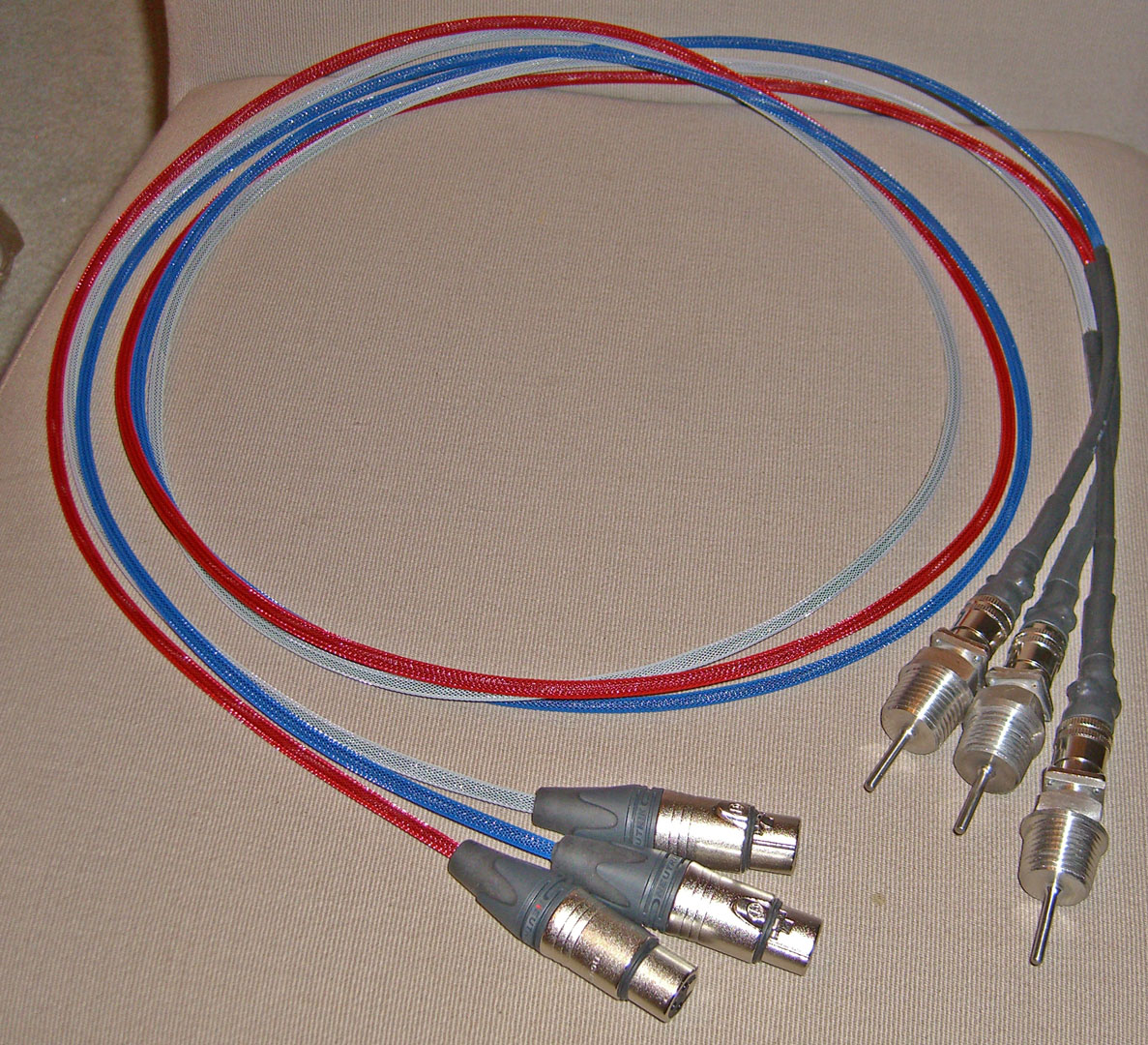
Temperatures will be controlled by a PID or proportional-integral-derivative controller. The ones I'm using are Auber SYL-2352 PIDs. The temperatures are monitored by the PIDs using a RTD or resistance temperature detector. I am using Auber Liquid tight RTD sensor, 1.5 inch, 1/2 NPT Thread sensors. I modified them slightly to be a bit more sturdy and to connect to my main control panel with XLR connectors. Here is what I did....
Temp probe parts
I started with a length of 1/32in wire rope, 2 pieces of 1/8in braided sleeve, a 3 pin XLR connector, the RTD probe and some heatshrink tubing.
I loosened the clamp in the probe end and looped the wire rope through it. This will help if the probe is ever accidentally tripped over or pulled.
I then pulled the black braided sleeve over the wire and then pulled another colored braided sleeve over that for 2 layers. Each probe has a layer of black and then another color over that. Then I tucked the ends of the sleeve under the clamp and tightened it down.
The end was then covered with 3 different sizes of heat shrink tubing.
On the control panel end, I put on a nylon tie wrap and then folded the wire rope over it and applied another tie wrap to secure it. The wires were then soldered to the XLR connector and connector was then closed up.
Here is a picture of the finished probes. One probe will go to each vessel and the other end will attach to the main control panel and inside will go to the PIDs.